Infill block plane

by Vittorio After the Infill Smoother I started to building a block plane. The initial draw will be lightly modified in progress. A new adventure begins.
I started from a steel bar (Fe 430, 40x4 mm). The sides were coupled and dovetails cut.
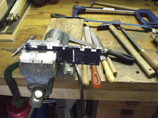
Because the low angle (13°) I divided the sole (6 mm tick) in two parts. This eases the file job for cutting the seat. In the following pics the sole layout, the bed cut and the joint execution
A aluminium wedge completes the iron bed and lightens the total weight.
  I used a smart phone app for measuring the slope: 13°, what I wished.
Arc soldering of sole parts; apart a little leakage (on the left), the bottom is ready.
The original draw was modified in reducing the central zone tails (where I welded) in order to avoid too much stress while hammering. The grinding by hand begins.
The aluminium wedge was bored and threaded for inserting a bar as blade depth adjuster.
Sole and wedge are joint by epoxy glue plus three M6 screws (with thread locker), spread out from bottom side.
Wooden pattern for iron adjuster
Before peening, I created secondary bevels in order to give more strength to spread out steel.
Tail peening, angle grinder for roughing, files, abrasive papers.
 Steel lever cap, 10 mm thick.
Ash posterior and anterior parts, mansonia and wattle wood lever cap screws.
Metal accessories: 6mm rivet, cylinder (10 mm ext., 6 mm int. diameter) for fixing the  front bun, blade adjuster.
Unfortunately, during the sole flattening some joint voids appeared and I had to fill them with metal plaster. No problem for strenght, but they do not look well.
I fixed the bun by spreading out the rivet, roughed out by filing and flattened by 80, 150 and 180 grit abrasive paper.
The plane has a Quangsheng block blade, honed with 25° bevel.The mouth width is less than 1 mm. 
The blade adjusting mechanism is formed by a M5x40 threaded bar, normal pitch, screwed and fixed (by a nut) into aluminium wedge; the blade is adjusted to the wished depth by screwing and unscrewing a lead nut
The assembled plane 
Read More..

Doors Ahoy!

Once the doors were sanded, I set on installing them. As I had previously dry fit each door with a single screw, the final fitting was fairly straightforward. I clamped the door to the hinge and sunk a screw into the hole from the dry fit.
A sanded door.
From there I alternated between my drill and screw gun, pre-drilling and screwing as I worked my choice down the hinges.
Doors Ahoy!
They installed fairly quickly and as the screws are set in the end and back faces of the ¾” baltic birch door panels, they seem more than strong enough.
Unfortunately, they’re also uneven. The left door sits about ?” higher than the right. I suspect that the unevenness was present and would have been noticed during my dry fit, had I had the presence of mind to check. As this point, I’m not 100% sure how bad the unevenness is (could be from racking of the carcass) and what I’m going to do about it (if anything). At this point I’m going to wait until I hang the cabinet on the wall and then I’ll see how the doors are sitting relative to each other with the cabinet hanging naturally. If it’s still choice off, I may try to clean it up.
So close, and yet . . . not.
Does your tolerance for error grow as project completion approaches too?
Other Bastard Wall Cabinet PostsWinter Wall Cabinet WonderlandThe Bastard Wall Cabinet (for tools!)Trudging Towards Tool StorageCutting the Cabinet Carcass (in relative terms)A Home For My PlanesContinued Wall Cabinet AssemblyWhats a Bastard Wall Cabinet without Shelves?
Boxing in the Bastard Tool Cabinet
Door Hinges on the Bastard Wall Cabinet
Oh, You Mean That Was Supposed To Lift?
Door Tops & Bottoms
Read More..

How To Design Furniture

In 2009 Taunton released a special issue of Fine Woodworking: How to Design Furniture.
image from Taunton.
As with most of their special issues, its a collection of previous articles, all focusing on a single topic.
In this case, I think they cove the topic of furniture design wonderfully. There are articles about styles, creativity, proportion, drafting and even SketchUp.
This has alchoices been one of my favorite design books. If you havent had a chance to read it, now is the time. Taunton has re-released it as a magazine special issue.  Id recommend you pick up a copy of the re-release. Its sure to prove a reference youll use long after the current print run is gone.
Read More..

Ghetto WorkCenter Boom Arm Part III The Boom Arm

As much as I love my TS55, I find keeping the vacuum hose clear of hangups to be the most challenging part of using it. Don’t get me wrong, I wouldn’t use the TS55 without the vacuum hose. It does a great job of capturing what I’d estimate to be about 85% of the dust.My old setup was to simply velcro the power cord to the vacuum hose. This meant there was effectively only one (1) tether being dragged by the saw, but in practice I have continually caught the hose on the side guards of my BenchMark Table, on the workpiece or on the track..
It cuts wonderfully, when the hose isnt getting caught.
My first attempt to remedy this issue was with the purchase of the Festool Guide Rail Deflector. The Guide Rail Deflector is a plastic piece that fits to the end of the Festool Guide Rail. It’s designed to prevent the hose and cord from getting caught up on the end of the guide rail. Unfortunately, it doesn’t keep the hose and cord on the rail, so they still fell to the side and caught on the BenchMark Table’s side guards and the piece being cut.The solution to keeping the hose out of the choice is a boom arm. I know from my previously built wall mounted boom arm, that they work wonderfully at keeping hoses and cords out of the choice. Unfortunately, the boom arm that Festool makes costs a bit over $300.00. For a short hose, a short extension cord and some steel tubing, that strikes me as much more than I’m willing to pay.
Looks as good a place as any to mount a boom arm.
Once I’d built the TS55 tray, it dawned on me that if I made a boom arm to fit on it I’d finally have my hose and cord out of the choice.
A simple boom arm.
I made the boom arm using scrap ½” baltic birch plywood. The pieces simply lap each other and are fastened with ¾” flat head screws. The arm attached to the support mast with small butt hinges. The hose is attached to the arm with small I-bolts, springs and plastic ties. Thanks to a suggestion by Chris Wong of Flair Woodworks, the hose will soon be attached via Wrap-N-Straps from Lee Valley.
The springs allow plenty of give in the hose.
To mount the boom arm to the saw tray, I attached a small hook to the back of the mast. It was notched so that it caught the side of the tray and prevented the boom mast from moving side to side. I then added a second hook that caught the inside of the lip on the tray. So that the mast would stand vertically, I added a spacer block at the bottom. It holds the bottom of the boom off the systainers the same ½” as the lip around the tray.
The initial hook allowed too much wobble.
While the initial hooks worked, I found that the mast and attached boom wobbled a bit more than I was comfortable with. I took off the initial second hook and replaced it with one the full width of the tray. Now the boom arm is rock solid.
The new hook is the full width of the tray for much more stability.
The completed boom arm holds the vacuum hose out of the choice during use. No more getting caught up half choice through a cut. It also mounts on and off the saw tray in moments.
The completed boom arm on the saw tray.
Now that my saw can no longer slide off the systainers, and the vacuum hose it up and out of the choice, what to do about the sanders?
Read More..